Download Press Release
The images in more detail
1 Introduction
In Germany, there are around 106,000 road bridges for public motor vehicle traffic. 67,000 bridges are under municipal ownership and maintenance obligation [1] while 39,500 are part of the federal trunk road network which, in turn, belongs to the national network of highways and main arterial roads [2]. A large proportion of all bridges is older than 40 years.
The high investment backlog regarding municipal bridges due to budget deficits in many municipalities is well known. In the report published by the German Institute of Urban Affairs, it is estimated that an investment of 10.7 billion euros will be required by the year 2030. On average, bridges that are the responsibility of the federal states and federal government are considerably larger than municipal bridges. The investment required here is likely to be even higher. Road construction authorities have calculated that upgrade requirements for the 400 major bridges on the federal highways in the state of North Rhine-Westphalia alone will cost 4.5 billion euros in the next 10 years.
Over 70% of the German bridges for public motor vehicle traffic are made of concrete. The expected investment in the coming years will flow mainly into the refurbishment of these bridges and thus also in the renovation of their parapets.
2 The construction of cantilevered parapets
Cantilevered parapets – also known as bridge parapets – form a boundary along the sides of a bridge. They have no direct static benefits. Apart from protecting the bridge sealings, their main purpose is to ensure a visually attractive lateral barrier. Parapets compensate for building inaccuracies that have arisen during construction. In addition, they provide space for pedestrians to cross the bridge and for installing lateral guardrails.
For the construction of cantilevered parapets with concrete cast in situ, a range of auxiliary construction aids made of wood or steel are used depending on the parapet geometry, bridge length as well as the type of bridge. The building contractor can draw on a number of system solutions from different providers in addition to the conventional carpenter-based solution.
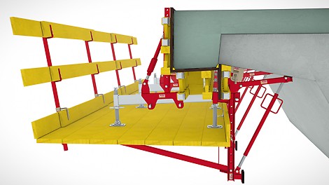
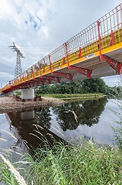
For longer bridges, movable systems with continuous constructions at the bottom or top are used. Concreting takes place here section by section (Image 1; Image 2). A further possibility is the use of immovable bracket scaffolds which are mounted along the entire length of the bridge. The cantilevered parapet can in this case be concreted in one piece (Image 3).
Securing all these systems to the bridge support structure must be carried out using building authority approved anchors. For new structures, the anchors can be embedded during the construction of the bridge in compliance with the required concrete covering. Their load-bearing capacity is usually very high and installation unproblematic.
For refurbishment operations, it is more difficult to realize suitable anchoring. The products that are available to the structural engineer in charge often result in very expensive, labour-intensive assembly and dismantling procedures, or they do not have the required load-bearing capacity.
In the case of brackets for the construction of bridge parapets, there have been only a few "closed system solutions" available up to now. In this context, a "closed system solution" is understood to be a type-tested bracket with perfectly matched components. Thereby, the type testing not only covers special cases but also takes into consideration typical construction site boundary conditions. The most important component of a "closed system solution" is the anchoring in the concrete which includes an approval. Ideally, this includes an installation solution for the new structure as well as a solution for subsequent anchoring, e.g. for refurbishment projects.
3 Special features to be considered when planning with cantilevered parapet brackets
3.1 Lateral inclination of the cantilever arm underside and the longitudinal inclination of the bridge
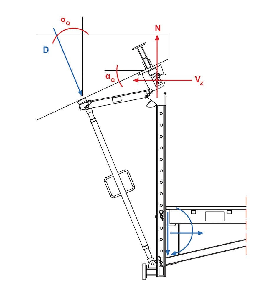
For constructions that are mounted to the underside of the lateral bridge cantilever arm, the inclination of the cantilever arm underside αQ (Image 4) and the longitudinal inclination of the bridge αL (Image 5) have a significant impact on the internal forces in the bracket scaffold. Another effect of the bridge inclinations are that additional loads are exerted on the anchoring. In particular, the additional tensile force is often greater than the tensile force that would result if the inclinations were disregarded. Therefore, the inclinations significantly determine the maximum widths of influence and, in turn, the maximum permissible bracket spacings.
The design charts and tables, which are placed at the disposal of the contractor by the bracket provider, should include details explaining how the longitudinal and lateral inclinations affect the bracket and anchoring forces. If this information is missing, separate static calculations must prepared for each individual case. This may result in considerable additional costs.
3.2 Anchoring for cantilevered parapet brackets
“The committee dealing with interdisciplinary issues relating to the suitability of use (GA 1) of the DIBt (German Institute for Construction Technology) decided in its meeting of 5th September 2001 that the proof of usability for the anchoring of climbing scaffold (consisting of climbing formwork and working platform) is to be provided by means of a general building inspectorate approval or approval in individual cases” [4].
The term "anchoring of climbing scaffold" refers to the temporary or permanent anchoring of bracket scaffolds which also includes climbing formwork, cantilevered parapet formwork and other special scaffolding.
Load transfer means (e.g. Scaffold Mounting Rings or Suspension Shoes), carry the load from the bracket into the anchorage. The eccentricities have to be taken into consideration whereby the internal loads could be significantly greater than the external loads. In some anchor approvals, it is therefore specified which bracket scaffolds and which load transfer means may be combined with the respective anchoring. Furthermore, they contain, among other things, details regarding the permissible scope of application, minimum concrete strength at the time of loading, required edge distances and anchoring depths as well as information on assembly and dismantling, or possible re-use.
Particular attention should be paid to the anchoring depth as very often this can no longer be checked after installation has taken place. A suitable anchoring system reduces potential misapplication and allows inspections to be carried out. When assembly work has been completed, the anchors are usually only partially removed again and tie holes sealed. It should be noted that the concrete cover for the steel parts remaining in the concrete of bridge support structures may not be less than the the minimum concrete cover.
Scaffold brackets are usually fixed to the embedded anchors by means of bolts or tie rods. The shear forces are transferred via the bracket into the anchor along the length of the concrete cover. Depending on the parapet geometry and according to the longitudinal and transverse inclinations of the bridge, resulting shear forces can be very high. Many tie rods are not approved which allows shear forces to be transferred or even to transfer moments. Furthermore, approved anchors are frequently used whose area of application does not correspond to the construction site situation.
For refurbishment projects, it is difficult to realize anchoring which take into consideration all regulations, static requirements, client requests and, not least, the views of the building contractor. Cost-effective solutions do not meet for the most part the requirements regarding concrete cover or load-bearing capacity. Solutions that fulfil the requirements concerning corrosion and load-bearing capacity are usually expensive or require increased assembly or dismantling effort.
4 Advantages of a closed system solution
4.1 VARIOKIT Parapet Brackets
The VARIOKIT Parapet Bracket is a cost-effective and very efficient system that can be used as a working platform as well as formwork bracket. Platform and formwork elements are separated in order to avoid any openings and open penetrations in the decking. As a result, the platform can be assembled in the form of a "closed trough" thus ensuring a maximum level of safety for the continuous flow of traffic below (Image 6, Image 7).
The individual components of the system are quickly and easily mounted as they each weigh less than 20 kg and can be carried and installed by one person. For safety reasons as well as improving the quality, operation and continuous adjustment of the slab and side formwork is carried out from the platform itself. With the brackets, bridge parapets with a maximum width of 60 cm and a maximum height of 100 cm can be constructed. In the process, the system needs comparatively few anchor points.
PERI provides the user with a type test as well as design tables and charts for inclined and non-inclined bridges. In addition, PERI engineers support customers with the planning and calculation of a project. For the contractor, this means planning reliability and cost savings – also because there is the option of purchasing individual components or renting them.
4.2 Refurbishment Anchor
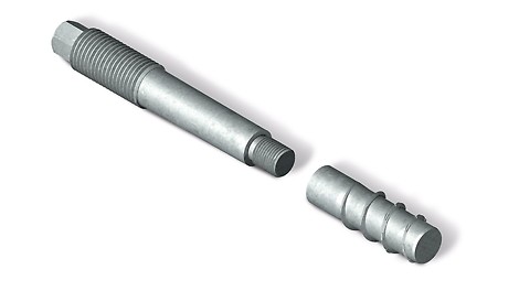
For its VARIOKIT Cantilevered Parapet Bracket, PERI offers two efficient and approved anchoring systems. On the one hand, there is the PERI Anchor Sleeve that is used in new building construction. On the other, the product portfolio includes a new type of concrete anchor which is mainly employed in refurbishment projects (Image 8).
As the refurbishment anchor has a very high load-bearing capacity, the number of anchor points needed can be considerably reduced. For assembly, the anchor requires only a relatively small hole to be drilled. Due to its undercut, the bracket can be mounted immediately. Slipping out during overhead installation is not possible. The anchor reaches its full load-bearing capacity as soon as the inserted composite mortar has hardened. Another advantage is that the anchoring depth can be checked during assembly and can also be verified subsequently.
The refurbishment anchor is divided into two parts (Image 8). It consists of an anchor bolt and an internal threaded sleeve. The threaded sleeve is the smaller part of the complete anchor; after the dismantling procedure, it remains in the bridge structure. The anchor bolt can be unscrewed and removed, and reused many times over (Image 9). During the dismantling of the auxiliary joining part, the anchor holes can be immediately sealed.
5 Summary
Determining the load transfer for cantilevered parapet formwork and brackets is very time-consuming. Even small changes in the boundary conditions as well as the internal and external eccentricities have a great impact on the internal forces in the load-bearing system and ultimately in the anchor loads. In the static calculation or in the type test, the bridge lateral and longitudinal inclinations in particular must be taken into consideration, in addition to the parapet geometry. Extrapolation of a special case to the actual conditions on the construction site is not possible.
The failure of a single bracket or anchor can lead to the total failure of the entire system with considerable risks for those persons on and under the bridge at the time. In order to increase safety on bridge construction sites, the anchoring is therefore required with approval.
For realizing parapets for new constructions as well as refurbishment projects, PERI has developed a flexible and efficient scaffold bracket that can also be used on bridges with steep lateral and longitudinal inclinations. For subsequent mounting on the structure, a new type of anchoring is available to the user which is optimized to meet the requirements of the respective construction site. All components used, up to and including the the anchors, are matched to each other. They are type-tested or have been officially approved.
The "closed system solution" guarantees maximum flexibility during the planning phase and application, increases planning reliability and work safety along with facilitating easier assembly. This leads to higher quality in the execution and ultimately cost savings for all involved.
Reference list
[1] Arndt, Wulf-Holger u. a.: Ersatzneubau Kommunale Straßenbrücken, Endbericht Deutsches Institut für Urbanistik (DIfU), Berlin, 20.9.2013
[2] Brücken an Bundesfernstraßen, Brückenstatistik, Bundesanstalt für Straßenwesen (bast), Bergisch Gladbach, 1.3.2015
[3] Zusätzliche Technische Vertragsbedingungen und Richtlinien für Ingenieurbauten (ZTV-ING), Gesamtfassung ), Bundesanstalt für Straßenwesen (bast), Bergisch Gladbach, März 2015
[4] Scheller, Eckehard: Konsolgerüst-Verankerungen brauchen bauaufsichtliche Zulassung, Allgemeine Bauzeitung, Ausgabe Nr.10, 11. März 2005


